The machine is Halo, a seven-foot orbital wrapper. This page is about how it was designed: a language model drawing a seven-foot machine, running tests against its own work, and the five places that went wrong anyway. Most of the wrong ones were mine.
The model is made out of the cutting files
This matters more than anything else on the page, so it goes first.
A CNC router needs a flat outline per part — where to cut, where to drill. A 3D model is a different thing: solid shapes you can look at and measure between. The normal way to get both is to draw the solid, then export flat outlines from it, and from then on you have two descriptions of the same machine that can drift apart.
This one runs the other way. One script produces the cutting files. A second script reads those outlines and extrudes them into 118 solids. Nothing is drawn twice. If the model says two parts clash, the files that would cut them clash, because the model is nothing but those files given thickness. A rule was written down early — never re-draw a part in the assembly — and it is the only reason any of what follows can be trusted.
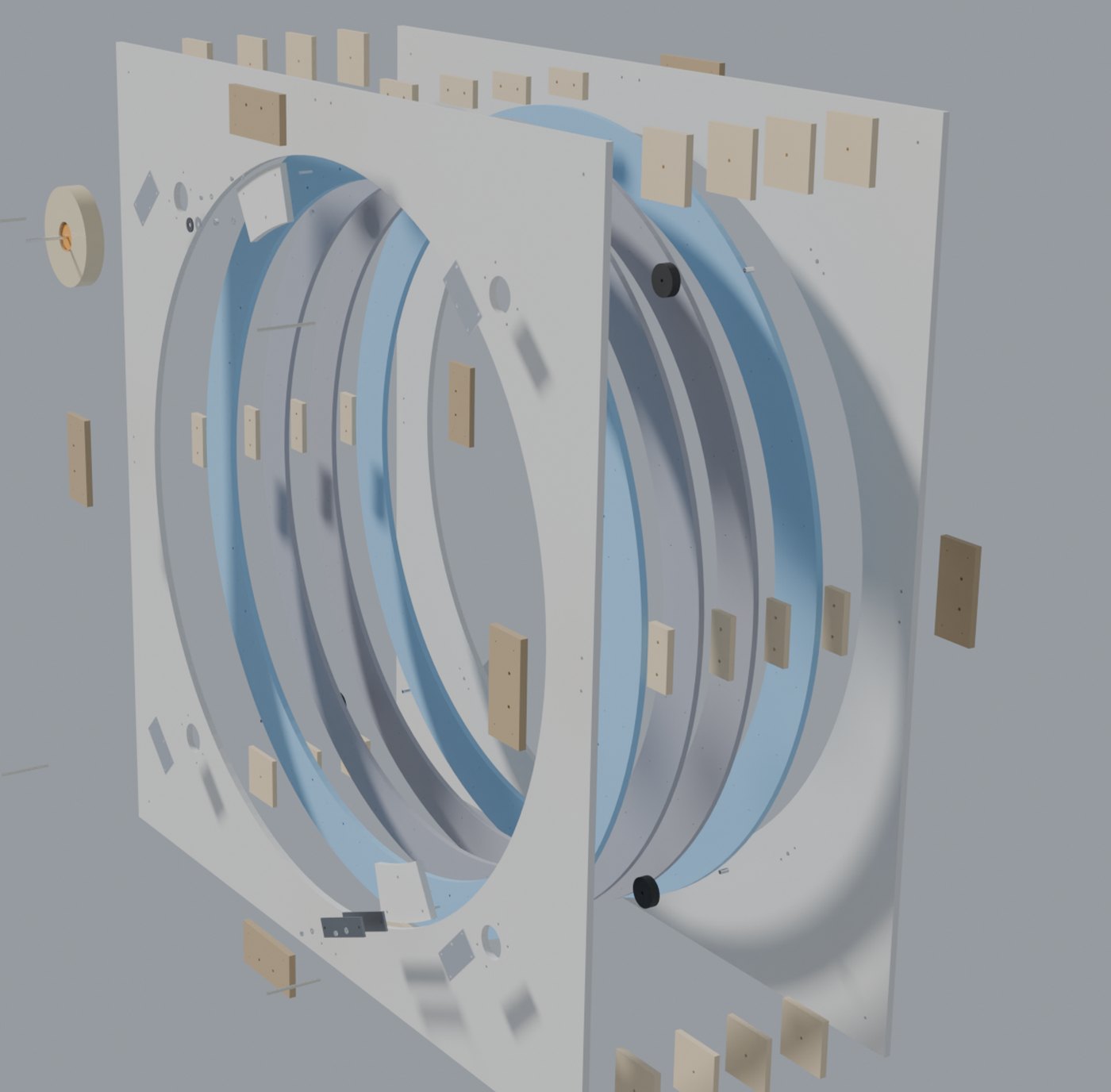
All 118 solids, pulled apart. Not one of them was modelled by hand. Each is an outline the router would cut, extruded to the thickness of the sheet it comes from — which is why the picture and the cutting files cannot disagree.
The model then tests itself. It looks for solids sharing space, measures the shortest distance between every pair that should not touch, weighs everything, and does it all again at each 15° of ring rotation. It also plants a failure on purpose: one wheel is shoved a millimetre into the ring to confirm the clash test can still see a clash. A test that has never failed has not been shown to work.
1. Twice the weight
The written plan guessed the ring at 55 lb and the whole machine at 200 lb. Those numbers were mine, from looking at a sketch.
The model weighed the real shapes at the real density: the ring is 99 lb and the machine is 264 lb.
Nearly double, and it changes things downstream. What turns the ring is a hand crank, and the gearing of a hand crank is chosen from the mass it has to start and stop. Every wheel load, every bolt size and the whole argument about whether a motor is safe had been reasoned from a number that was wrong by half, and that number sat in a written plan for a day before anything measured it.
2. The check that was wrong about itself
One clearance came back at 1.10 in: the gap between the outside of the ring and the blocks that hold the two panels apart.
It was not 1.10. The test was measuring to the corner of the block, and the corner is not the part of the block nearest the ring — the middle of its inner edge is. The true gap is 1.00 in.
Nothing had to be redrawn; no cutting file changed. But for a while the machine carried a number that was 10% optimistic, produced by software, printed in a column of figures that all looked equally solid. The lesson is not about geometry. A test that returns a number always returns a number, and it will keep returning it whether or not it is measuring the thing you think.
3. The plate that hung over the edge
The ring is too big to cut from one sheet, so each layer is four segments, and the seams get a plate bolted across them on the outside.
The plates were drawn centred on the bolts they share with the blocks behind them. That was the obvious place to put them. It also pushed each plate 0.75 in past the edge of the panel, hanging in the air, catching a sleeve.
No test caught this. Every clearance passed, because nothing was in the way — being in the way is what tests look for, and this plate was in the way of nothing. I found it by looking at a picture of it.
The fix was not moving the plate. The fix was adding the test: the model now fails if a splice plate passes the panel edge. The plate kept its size and its bolt holes moved off-centre. A bug found by eye and not turned into a check is a bug you have agreed to find again.
4. How do you change a wheel?
The four skate wheels are the only wearing parts in the machine. So: how do you change one?
Nobody had asked. The drawing does not ask — a drawing shows the machine built, not the machine opened. When the question finally got put to the model, the answer came back ugly. The ring’s two outer layers stand proud of the middle ones, forming the channel the wheel runs in, and that lip overlaps the wheel by 0.75 in on both sides. The wheel cannot be lifted out. The nearest edge it could be slid out through is about sixteen inches away, and the panels are glued, so opening the machine means cutting a new panel.
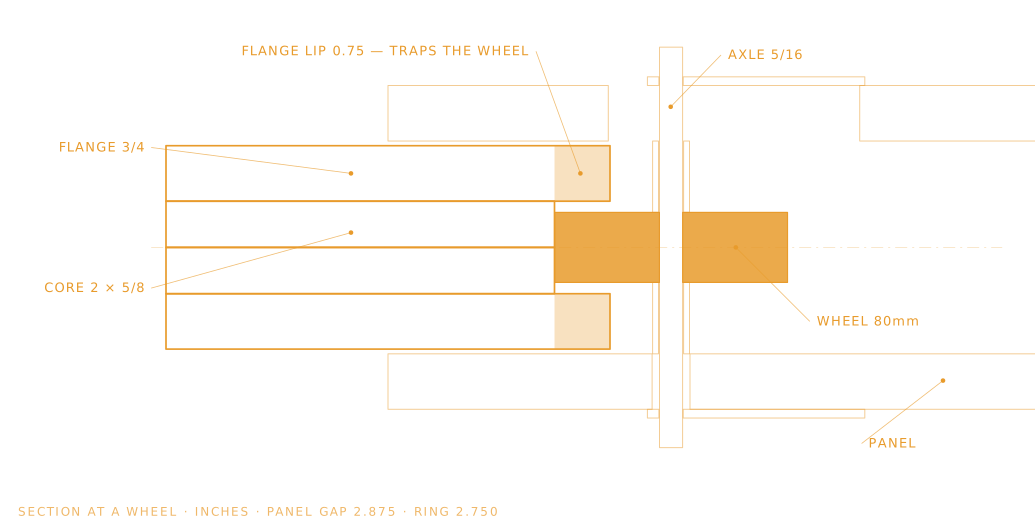
The answer was a hole: a 3.4 in port through the front panel at each wheel, covered by the wheel’s own mounting bracket. Take the weight off the ring, unbolt the bracket, pull the axle, slide the wheel outward until it clears the lip, lift it out through the port.
That sequence was then simulated in quarter-inch steps to confirm it clears — and, because the last section was written, it was simulated the wrong way too. Lifting without sliding first hits the front lip, exactly as it should. Both answers were needed. One of them is the only evidence the other means anything.
5. The fix opened a new hole
The brackets that cover those ports are cut from aluminium rail the shop already has, and the rail is narrower than the port.
So each port is not fully covered. A crescent about half an inch deep stays open, on the ring side, right at the wheel — which is the exact spot where a turning ring and a fixed wheel meet, and the exact spot a finger should never be. A repair access hole had turned into a pinch point.
It is recorded as a requirement on a part that does not exist yet: the wheel guards must cover the crescent. Not solved. Written down where it cannot be quietly forgotten, which is the most that can honestly be claimed for it today.
What the model was good at, and what it wasn’t
It was good at what does not fit through what. It found the wheel channel could not be a single layer of board because a skate wheel is wider than a board is thick. It found that the 72 in hole is really a 56 in hole once a roll of tape is hanging inside it. It weighed 118 solids without complaint and it never got bored of re-running the clash test at every 15°.
It was bad at questions nobody asked it. It will check whether the machine can be built. It will not spontaneously ask how the machine gets repaired, or what happens to the hand reaching past the guard, or whether a plate hangs off an edge into a walkway. Those came from a person standing in a shop imagining using the thing.
Where it stands
Every flat part has a cutting file. The stand, the crank and the guards are not drawn. Nothing has been cut, and the first thing cut will not be a part — it will be two test pieces, to find out what the router really does before a sheet becomes a seven-foot circle.
I expect that to find something else I was sure about. It usually does.