I wrote my own CAM — the software that plans a cutter’s route through the material — for a benchtop mill, and built a simulator to check its work. This is the first thing the simulator found.
The first version drew its toolpaths in the browser. They looked fine, and I trusted them.
Then I built a simulator that reads back the posted file — posted meaning it has been through the post-processor, the step that turns a planned route into the G-code the machine reads. So it is the file the machine will run, not the plan that produced it. I pointed it at a program every existing check had passed.
It found 43 places where the cutter drove straight down into solid material at full depth, like a drill rather than a mill. The cutter was a ball mill: a tool with a rounded tip, meant to sweep sideways across a surface, and nearly useless at cutting downward. Those 43 dives made up 72.7% of the job. That is how you snap a ball mill.
They had been invisible for two reasons. All 43 dives happened at the same spot on the table, so the drawing stacked them into a single vertical line, which renders as nothing. And the drawing came from my software’s own plan — the data it held in memory before the post-processor touched it. It could never have revealed a post-processor mistake, because it had never read the post-processor’s output.
The drawing a program makes of itself is not evidence. Read back the file the machine will run.
Everything since builds on that. The simulator reads the G-code line by line, rebuilds a model of the block as it is eaten away, and checks what the file would do to the cutter, the material and the clamp.
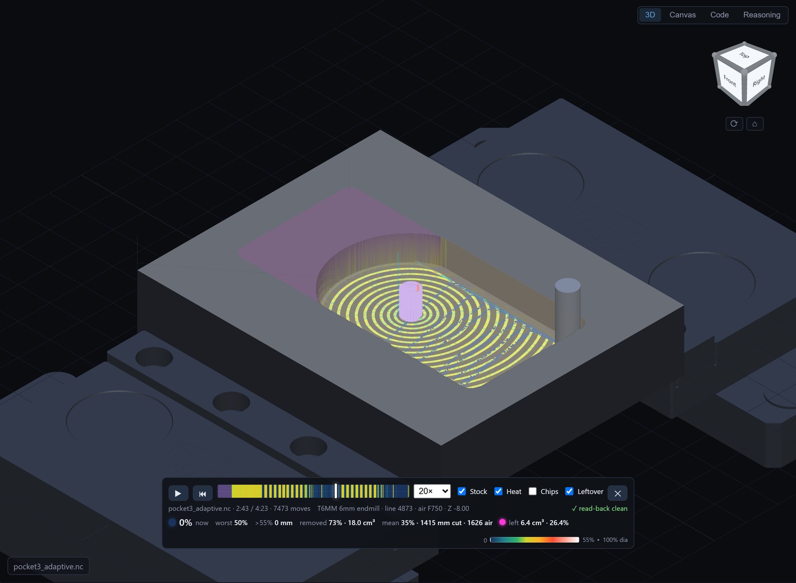
The simulator on a test shape held in the modelled vise. Each ribbon is one pass of the cutter. The green line at the right reports that the finished G-code passed every check.
It also grades the job on one number. At every moment, some fraction of the cutter’s width is buried in material — its engagement. That number is the whole game. Bury too much of the cutter and it chatters, bends, or breaks; bury too little and you are paying for cutting time you aren’t using. I set the limit at 55%. Every comparison in this series is measured against it.
Then the reference found my checks wrong
The obvious way to find out whether homemade toolpaths are any good is to run the same job through the commercial tool and compare. I ran six operations through Autodesk Fusion 360, and Fusion found three of my checks wrong before I found anything wrong with Fusion.
Two of them couldn’t tell air from metal. They looked at where the cutter went but not at whether anything was still there to cut, so they flagged harmless moves through space an earlier pass had emptied. The third applied a single depth-of-plunge limit to every cutter — wrong, because a ball mill and a flat-bottomed mill have different rights to move downward.
Two of my checks have no counterpart in Fusion, and both come from the particular machine in my shop. Fusion posted a cut 50.5 mm deep for a cutter with 10 mm of cutting edge — past that depth it isn’t the cutter touching the part, it’s the holder. And it posted tool-length offset commands: instructions that tell the machine to look up how far the current cutter sticks out. Bigger machines keep that table. Mine doesn’t. It has no tool changer and no stored tool lengths, so after every cutter swap I jog the new one down by hand until it touches the material and tell the machine that height is zero.
Neither is a Fusion bug. It is written for machines that have tool changers and offset tables, and it has no way to know that mine has neither.